THM-1 is a small temperature and humidity meter I designed this autumn: an STM32L031, a Sensirion SHT45, a 1.54-inch e-paper display and two AAA cells, on a 78 × 36 mm two-layer board. The goal is more than two years on one set of batteries, which shapes almost every decision on the board.
One of those decisions was to switch the display's supply off completely between updates. E-paper keeps its image without power, so a P-channel MOSFET (an AO3401A) cuts the display rail, and the MCU drives its gate straight from a GPIO pin. It is a common pattern and it looked fine on the schematic.
Simulating the boring part
Before ordering boards I ran the power path through ngspice with a battery model that includes internal resistance: fresh cells at 3.1 V and 0.3 Ω, half-empty at 2.6 V and 0.8 Ω, nearly flat at 2.3 V and 1.5 Ω. The display module's input capacitance is not published, so I swept it from 4.7 to 22 µF.
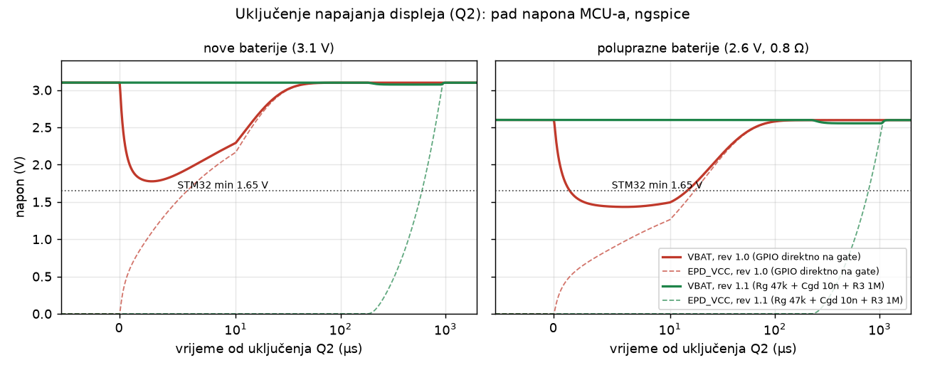
The problem showed up the moment the MOSFET turned on. Driven directly from a GPIO, it switches in nanoseconds. The display side's capacitors then charge from the small capacitance on the battery rail faster than the battery itself can refill it, so the rail the MCU sits on collapses.
| Batteries | Rev 1.0 minimum | Time below 1.65 V | Rev 1.1 minimum |
|---|---|---|---|
| Fresh (3.1 V) | 1.76–1.83 V | 0 µs (barely) | 3.05–3.08 V |
| Half-empty (2.6 V) | 1.43–1.47 V | 7–27 µs | 2.52–2.57 V |
| Nearly flat (2.3 V) | 1.27–1.29 V | 22–68 µs | 2.19–2.25 V |
The STM32L031 needs 1.65 V. With fresh batteries the design squeaks through, which is exactly why a bench test would have passed. Halfway through the battery life, every display update would have reset the microcontroller, and the device would have looked like it had a firmware bug.
Two fixes, and why hardware won
A firmware workaround was possible for boards already built. Raise the clock, then pulse the gate low for 0.25 µs every 20 µs, 150 times. That charges the display rail in small steps over about 3 ms, after which the switch can stay on. In simulation this kept the rail above 2.05 V even on nearly flat cells. It works, but it puts timing-critical, analogue-sounding behaviour into firmware. It depends on the clock, it breaks if someone refactors the GPIO code, and the 0.5 µs variant is already noticeably worse.
The hardware fix is three passive parts:
- a 47 kΩ resistor in series with the gate,
- a 10 nF capacitor from gate to drain, which slows the switching edge (a classic soft-start),
- the gate pull-up raised from 100 kΩ to 1 MΩ.
The display rail now rises over roughly a millisecond instead of nanoseconds, and the battery rail dips by at most 0.11 V across all battery states and tolerance corners. Revision 1.1 has it, and the firmware stays simple.
What I took from it
- Model the source, not just the load. With an ideal battery the simulation shows nothing. Internal resistance and its growth over the battery's life is the whole story.
- Test where the product spends its life. "Works with fresh batteries" describes the first week of a two-year product.
- Prefer the fix that can't be refactored away. A timing trick in firmware is a requirement that nobody will remember in a year. Three resistors and a capacitor on the schematic document themselves.
The same simulation pass produced a less dramatic but useful number: the display accounts for about 95 % of the energy budget. Updating it only when the reading actually changes matters far more than any sleep-mode tuning on the MCU.